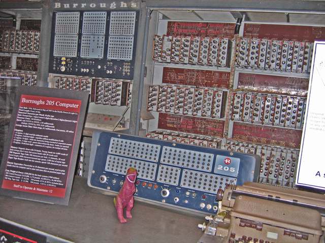
John Alrich, the engineer who implemented the Datatron control unit, described the machine in considerable detail in an article in the March, 1955 Transactions of the I.R.E. Professional Group on Electronic Computers. He stated that there were 173 circuit packages in the Datatron of twenty-three standard types. Fifty-eight percent of the packages were of two types: the Flip-Flop package, and the Blocking Oscillator package.

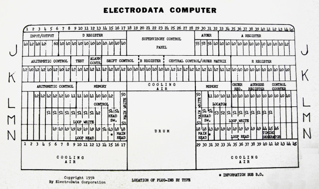
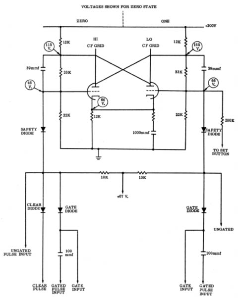
Each of these packages contained eight dual-triode vacuum tubes. The Flip-Flop package held four dual triodes forming the actual flip-flops and four dual triodes configured as cathode followers. The cathode followers isolate the flip-flops and provide a low-impedance output. The Flip-Flop package formed one decimal digit of each register. The Blocking Oscillator package also contained eight dual-triodes configured as four blocking oscillators with a cathode follower and "puller" tube in front of the actual B.O.
Here is a circuit diagram for one of the flip-flops in
the Flip-Flop package:
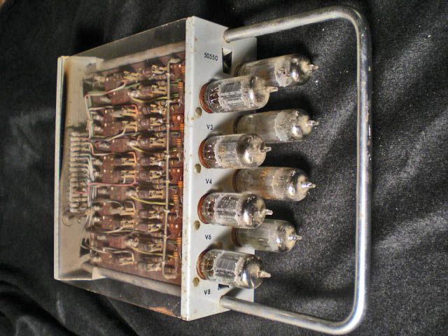
Bob Kubic worked as a programmer at Babcock and Wilcox in Lynchburg Virginia. They had a Datatron that was used to design the Indian Point I nuclear power station, the nuclear merchant ship Savanna, The Liquid Fuel Reactor experiment, and various design studies that led to the next generation of reactors. Bob still has one of the B-register decade packages from that machine. He shared these pictures of it.

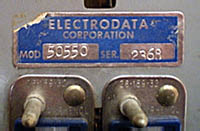
(Left photo, TJS. Center and right photos courtesy of
Bob Kubic, November, 2008)
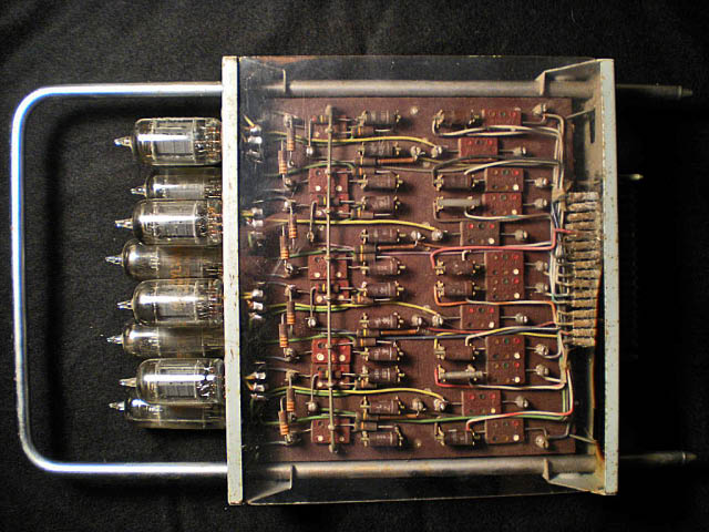
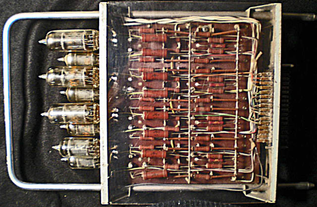
(Photos courtesy of Bob Kubic, November, 2008)
These two photos show the layout with most of the capacitors and diodes on one sided of the printed circuit card and most of the resistors on the other side. The resistors generated more than a little design headache and controversy. Note the large number of 1% precision resistors. The added cost over using 5% resistors in the voltage divider area of the circuits was estimated at $600 per computer. The tradeoff, though, was greater tolerance to tube aging so the decision was made to go with the 1% resistors.
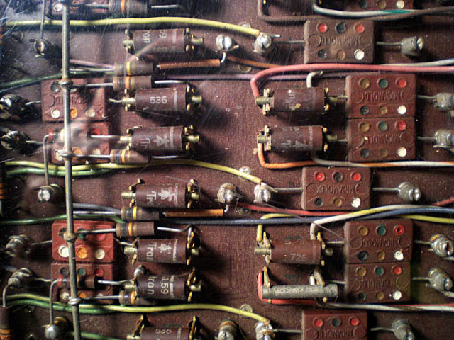
(Photo courtesy of Bob Kubic, November, 2008)
Note the diode clips in this photo. These were also controversial. Both of the ElectroData consultants weighed in on the inadvisability of using clips versus soldering in the diodes. Harry Huskey was concerned that diode clips had not been reliable in his past experience. Since Huskey was already a veteran of at least four computer construction projects at this point in early 1952, his concerns were taken seriously. Ernst Selmer took the issue to Julian Bigelow at Princeton, chief engineer on the IAS computer. Bigelow thought these clips looked solid but he and Selmer were still concerned that they could lead to errors and recommended experimentation to identify the potential for trouble.
Do you have comments or experience with the Burroughs 205 that you would like to share? I have set up a blog where you can share your own stories about the Datatron. Or, send me an e-mail.
